database normalization
Process Device Database ( review )
- Collect requirement of user / business.
- Developing E-R Model pursuant to requirement of user / E-R business.
- Converting E-R Model to relationship gathering.
- Relationship normalization to eliminate anomaly.
- Implementation to database by making table to each relationship which have normalization
Normalization Database
Normalization is process forming of database structure so that most ambiguity can be eliminated. Phase Normalization started from lightest phase ( 1NF) till tightest ( 5NF). Usually only coming up with level 3NF or BCNF because have adequate enough to yield the tables which goodness quality.
why done normalization ?
- Optimalisation Structures of tables
- Improving speed
- Eliminating inclusion of same data
- More efficient in usage of storage media
- Lessening redudansi
- Avoiding anomaly (insertion anomalies, deletion anomalies, update anomalies).
- improved Data integrity
A tables told goodness ( efficient) or normal if fulfilling 3 criterion follow this
- If there is decomposition of tables, hence its of him have to be secured ( Lossless-Join Decomposition). Its Meaning, after the tables elaborated / decomposition become new tables, the new tables can yield tables initialy same precisely
- The looking after of depended functional at the (time) of change of data ( Dependency Preservation
- Do not impinge Boyce-Code Normal Form ( BCNF)
If third criterion ( BCNF) cannot fulfilled, hence at least the tables do not impinge Normal Form of third phase ( 3rd is Normal Form / 3NF).
Functional Dependency
Functional dependency (FD) is a restriction that comes from the meaning of attributes and relationships between attributes. Functional Dependency attributes describe the relationship in a relationship.
Symbol that is utilized is –> for representing functional dependency.
–>Read functionally determines.
Notation: A –>B
A and B is attribute of one table. It means that functionally A determines B or B depend on A, if and only if available 2 rows data with same value of A, therefore value of B also same.
Notation: A -/-> B or A x –>B are opposite of previous notation.
gaya jak…

Functional Depedency ~ 4
Functional Dependency of the table value :
– Nrp -> Name
Because for each value Nrp the same, then the value of the same name
– (Mata_kuliah, NRP) -> Value
Because the value of attributes depending on the NRP and Mata_kuliah together. In another sense Mata_kuliah for the NRP and the same, they also rated the same, because Mata_kuliah and the NRP is a key (is unique).
– Mata_kuliah -//-> NRP
– NRP -//-> Value
Normal Form
1. The normal forms (abbrev. NF) of relational database theory provide criteria for determining a table’s degree of vulnerability to logical inconsistencies and anomalies. (from http://en.wikipedia.org/wiki/Database_normalization)
* First Normal Form (1NF) A table on the form said to be normal I if it’s did not reside in the unnormalized form of a table, where there is a kind of field multiplication and field that allows a null (empty)
Is not allowed there:
– Many attributes of value (Multivalued attributes).
– Attributes composite or a combination of both
So:
Price is the domain attribute must be atomic rates
Eg Student Data as follows:

or

the tables above does not meet the requirements 1NF
both tables are decomposition into:
Student Table:

Table Hobbies:
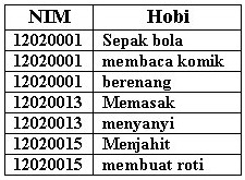
* Second Normal Form (2NF) ~ 1 – Normal form 2NF met in a table if it meets the form of 1NF, and all the attributes than the primary key, have a full Functional Dependency on primary key
– A table does not meet 2NF, if there are attributes that it’s Functional Dependency are only partial (only depending on the part of the primary key)
– If there are attributes that have no dependence on the primary key, then the attributes must be moved or removed
* Second Normal Form (2NF) ~ 2 – Functional dependency X -> Y is full if it is said to delete an attribute A from X means that Y is no longer dependent functional.
– Functional dependency X -> Y said if deleting a partial attribute A from X means that Y is functionally dependent.
– Relation scheme R in the form 2NF if every non-primary key attribute A e R depend on the full functional primary key R.
EXAMPLE:
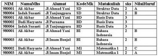
The following table meet 1NF, but not include 2NF
the tables above does not meet 2NF, because (NIM, KodeMk) is regarded as the primary key:
{ NIM, KodeMk } -> NamaMhs
{ NIM, KodeMk } -> Address
{ NIM, KodeMk } -> Matakuliah
{ NIM, KodeMk } -> SKS
{ NIM, KodeMk } -> NilaiHuruf
Table in the decomposition needs to be some of the table is eligible 2NF
their functional dependency as follows:
– {NIM, KodeMk} -> NilaiHuruf (fd1)
– NIM -> {NamaMhs, Address} (fd2)
– KodeMk -> {Matakuliah, SKS} (fd3)
So that:
– fd1 (NIM, KodeMk, NilaiHuruf) -> Value Table
– fd2 (NIM, NamaMhs, Address) -> Table Student
– fd3 (KodeMk, Matakuliah, SKS) -> Table MataKuliah
Third Normal Form (3NF) ~ 1 Normal form 3NF fulfilled if the form meets 2NF, and if there are no non-primary key attribute that has a dependence on non-primary key attributes of the other (transitive dependencies)
EXAMPLE:
The table following students eligible 2NF, but does not meet 3NF

Because there are non-primary key attribute (ie, City and Provincial), which has a dependence on non-primary key attributes of the other (ie KodePos):
KodePos -> { City, Province }
So that the table in the decomposition needs to be:
– Student (NIM, NamaMhs, Road, KodePos)
– KodePos (KodePos, Province, City)
Boyce-Codd Normal Form (BNCF) Boyce-Codd Normal Form constraint has a stronger form of the Normal third. To be BNCF, relations must be in the form of First Normal form and forced each of the attributes depends on the function in the super key attributes.
In the example below there is a relationship of seminar, is the Primary Key NPM + Seminar.
Students may take one or two seminars. Each seminar requires 2 each of the students and led by one of the 2 seminar. Each leader can only take one seminar course. NPM in this example and show a Seminar Pembimbing
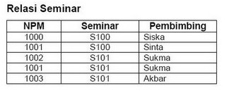
Relations Seminar is a form of Third Normal, but not BCNF, because Seminar Code still depends the function on the Pembimbing, if any Pembimbing can only teach a seminar. Depending on the seminar is not a super key attributes such as required by BCNF. So Seminar relations must be parsed into two tables:

Fourth Normal Form (4NF) and Fifth Normal Form (5NF)
– Relations in the fourth normal form (4NF) if the relation in BCNF and does not contain a lot of dependence values. To remove the dependency of many values from a relation, we divide the relationship into two new relations. Each relation contains two attributes that have a lot of relationship value.
– Relations in fifth normal form (5NF) deal with the property called the join without any loss of information (lossless join). Fifth normal form (also called the 5 NF PJNF (projection join normal form). The case is very rare and appear difficult to detect in practice.
Refrences
1. Agus Sanjaya ER, S.Kom, M.Kom ,presentation slide : Normalization
2. http://en.wikipedia.org/wiki/Database_normalization
database and entity relationship diagram
database and entity relationship diagram
the definition of database
* collection of data which stored in magnetic disk, optical disk or other secondary storage
* collection of data which is linked one to other of an enterprise.(factory, govermental institution, or private section)
* manufactur company -> production planning data, actual production data, data ordering material
* hospital -> data of patient, doctor, nurse, etc
database management system
* collection a database with software application in based of database
* this software application is use for accessing and maintaining the database
* the first aim of DBMS is to preparing an easy and efficient environment for using, collecting, and storing data and information
bit, byte, field
* bit : is the smaller part of data, which contain of value 1 or 0
* byte : collection of same kind of bit
* filed : collection of same kind of byte, which in database is called “attribute”
types of attribute
– single vs multivalue
- single -> only can containing mostly 1 value
- multivalue -> can containing more than 1 value with same kind value
– atomic vs composition
- atomic -> cannot divided into smaller attribute
- composition -> alliance of smaller attribute
– derived attribute -> attribute that can be yield from other attribute value, for example : age can be yield from attribute of birth datenull
– value attribute -> attribute with no value for a record
– mandatory value attribute -> attribute that must have a value
record or tupple
– a data row inside a relation
– consist of attribute collection which attribute interaction for advising entity or relation as detail
entiry or file
– file is collection of record that have same kind and same element, which the same attribute, but different data value.
– Type of file
In application process, file can be categorized as :
- Main file
- Transaction file
- Report file
- History file
- Protector file
- Activity file
Domain
– collection of value that can be inside one or more attribute.
– Each attribute in database relation defined as domain.
Element key of data
– Key is element of record that used for finding its in access time or can be used for identification each entity/record/row.
SPECIES OF KEY
There are several types of key in the ERD, namely:
- Superkey is one or more attributes of a table that can be used to identify entityty / record of the table are unique (not all attributes can be superkey)
- Cadidate Key is a super key with minimal attributes. Candidate must not contain a key attribute of the table so that the other candidate key is certain superkey but not necessarily vice versa.
- Primary Key One of the key attributes of the candidate can be selected / specified a primary key with the three criteria, namely:
1. Key is more natural to use as reference
2. Key is more simple
3. Key is guaranteed unique
- Alternate Key is the attribute of the candidate key is not selected to be primary key.
- Foreign Key is any attribute that points to the primary key in another table. Foreign key will be going on a relationship that has cardinality one to many or many to many. Foreign key is usually always put on the table that point to many.
- External Key is a lexical attribute (or set of lexical attributes) that values are always identify an object instance.
ERD (Entity Relationship Diagram)
ERD is a model of a network that uses word order is stored in the abstract system.
Differences between the DFD and ERD, namely:
1. DFD is a model of network functions that will be implemented by the system.
2. ERD is a model that emphasizes the network data on the structure and relationship data.
element in ERD
* entity
In the ER Diagram, Entity is described with the form of a rectangle. Entity is something that exists in the real system and the abstract where the data stored or where there are data.
* relationship
In the ER diagram, the relationship can be described with a rhomb. Relationship is a natural relationship that occurs between entities. In general, the name given to the verb base making it easier to do the reading the relation.
* relationship degree
Relationship degree is the number of entities which participating in a relationship. Degree is unit which is often used in the ERD.
* attribute
Attribute is the nature or characteristics of each entity and relationship
* cardinality
Cardinality indicates the maximum number of record/tuple that can be relation with the entity on the other entity
degree of relationship
* Unary relationship
is the relationship model between the entity originating from the same entity set.
* binary relationship
is the relationship model between 2 entities
* ternary relationship
is a relationship between the instance of 3 types of entities are unilateral
cardinality
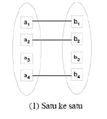
* one to one
Level one to one relationship with the one stated in the entity’s first event, only had one relationship with one incident in which the two entities and vice versa.
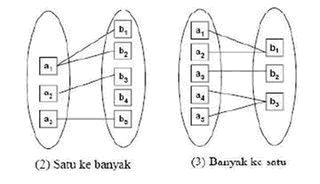
* one to many or many to one
Level one to many relationship is the same as the one to many depending on the direction from which the relationship have to seen.For an incident on the first entity can have many relationships with the incident on the second entity, if the one incident in which two entities can only have a relationship with one incident on the first entity.
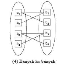
* many to many
if any incident occurs in an entity has many relationships with other entities in the incident.
example:
Notation (E-R diagram)
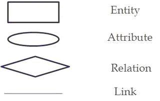
Symbolic notation in the ER diagram, namely:
1. Rectangle represent the collective entity
2. Circle represent the attributes
3. Rhomb represent collective relationships
4. Line as the set of relationships between the entity and the collective entity with the attribute
Reference:
- ER Ngurah Agus Sanjaya. Slide Part 5 – DATABASE DAN ER-DIAGRAM.
- Elmasri & Navathe, Fundamental of Database Systems, 5th Edition, Chapter 3, 2007.
DATA FLOW DIAGRAM
Data flow diagram illustrate how data is processed by a system in terms of inputs and outputs, describe the distribution of the modules in the system to a smaller .Easy to understand the less the field to understand the computer system that will be done. Data flow diagrams can be used to provide a clear representation of any business function. The technique starts with an overall picture of the business and continues by analyzing each of the functional areas of interest. This analysis can be carried out to precisely the level of detail requird. The technique exploits a method called top-down expansion to conduct the analysis in a targeted way.
A data-flow diagram use to make easy delineation a system a new one that will be developed logically without care physical environmentally where that data is adrift or environmentally physical where that data will be kept, therefore we utilize Flow’s Data or Data flow diagram diagram. Diagram grooves data constitute tool that adequately popular present, since gets to figure data current in a system with most structure and is clear, that is why DFD constitute the most assistive tool necessary for a system analyst. DFD purpose as tool of system display popularized by Tom DeMarco (1978) and Gane & Sarson (1979) by use of analisis sitem’s method approaching most structure (structured system analysis method). DFD that figured can auto and also manual system by use of image which gets graph network form.
Data-Flow Diagram (DFD)
· Also Called Data Flow Diagram (DFD)
· Figuring system division into smaller module
· Making user that have no a lot of knowledge of computer for understands system who will be develop
<!-
Data Flow Diagram Consisting of:
1. Context Diagram:
· Consisting of one process and figures scope of a system
· Constituting supreme level from DFD that what does figure all input that goes to system and output of system
· System drew the line by boundary (figured by dotted line)
May not there is stored (storage)
1. Zero Diagram
· Describe the process of the DFD
· Provide views on the overall system in which, showing the main function or process that is, the flow of data and entity eskternal
· At this level of data storage possible
· For processes that do not detailed again on the next level then added the symbol ‘*’ or ‘P’ at the end of the process
· Input and output balance (balancing) between 0 to diagram context diagram should be maintained
2. Detail Diagram
· Decompose a process that is in the diagram zero level or above
· In the one level there should be no more than 7 units and the maximum of 9, when more should be done in the decomposition
· Each process in the DFD must have a specification process
· At the top level method is used to describe the process can use a sentence with descriptive
· On a more detailed level, namely on the bottom (functional primitive) requires specification of a more structuredspecification process will be the guideline for the programmer to make this program (coding)
· Methods used in the specification process: the process of disintegration in the form of a story, decision table, decision tree
3. Process Spesification
· Each process on DFD must have process specification .
· On top level methodics that is use to figure process can by use of descriptive sentence
· On more detail level which is on lowermost process (functional primitive) needing more structure specification .
· Specification processes will be guidance for programmer in make a program (coding)
Method that is utilized in specification processes: breakdown of process in shaped story, table decision , tree decision.
4. Outer Unity
· Something system outboard, but it gives data into system or gives data of system
· Notation with notation box
· External entity excluding part of system
· Naming: Terminal name as substantive as Terminal may not have same name excepts the same object.
5. Data Flow
§ It is a place flowed the information
· described the straight line that connects the components of the system
· Flow data is shown with the direction arrows and the name on the flow of data that flows
· Flow data flow between processes, data storage and data flow indicates that the form of data input for the system
· Guidelines of the name:
1. Name of the flow of data that consists of some words associated with the flow lines connect
2. No flow data for the same and the name should reflect its content
3. The flow of data that consists of several elements can be expressed with the group element
4. Avoid using the word ‘data’ and ‘information’ to give a name to the flow of data
5. Wherever possible the complete flow of data is written
§ Terms of others:
1. Name of the flow of data into a process may not be the same as the name of the data flow out of the process
2. Data flow into or out of data storage does not need to be given a name if: Flow of data simple and easy to understand, Flow of data describing all the data items
3. There can be no flow of data from the terminal to the data storage, or vice versa because the terminal is not part of the system, the relationship with the terminal data storage must be through a process
Name application guidance:
· Data streaming name which consisting of umpteen flow word to be linked by interlocking line
· May not there is streaming data which its same name and name application shall reflect its content
· Data flow that consisting of umpteen element gets to be declared for by element group
Other rule:
· Data streaming name which turn in at a process may not same by the name of secretory data flow of that process.
· Flow’s data in or out from storage’s data not necessarily been given name if:
§ Simple data flow and perspicuous
§ Data flow figures all item’s data
· May not there is streaming data of terminal go to storage’s data or on the contrary since terminal is not part of system, terminal relationship with data storage shall pass through process
6. Process
· Process constitutes what do be worked by system
· Process can process data or input data flow become data flow come out
· Process functioninging to transform one or many entry data become one or many output data correspond to desirable specification
· Each process has one or many entries and resulting one or many outputs
Frequent process is called bubble.
Name application guidance processes:
· Name processes consisting of job and noun word that reflect that process function
· Don’t utilize process word as part of name a bubble
· May not there is many process that have same name
· Process shall numbered. Number thread as much as can follow flow or process thread, but such number thread doesn’t mean absoluting to constitute chronological process thread .
Data Storage:
· Storage’s data constitute aught data repository in system
· Is figured with a couple equal line or two line with incorrect single-sided sideways exposed
· Process can take data from database or insert data to database
· Name application guidance:
o Name shall reflect storage’s data
o If its name more than one word therefore has to be hyphened
DFD Symbol:

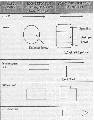
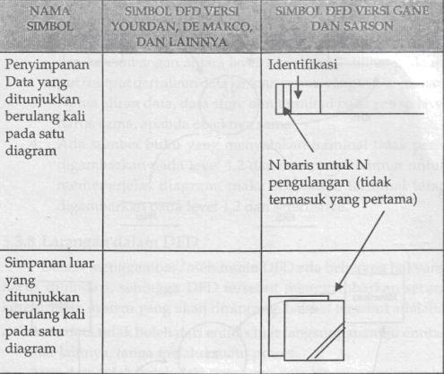
· Data flow that turns in and out from one process must equal data flow that turns in and out of details of process on level / level under it
· Data streaming name which turn in at and out from one process must have with by the name of data flow that turns in at out from details of that process
· Total and entitas’s name extern of a process must to equal total and entitas’s name extern of details of that process
· Things who shall be noticed on DFD who has more than one level:
o Shall available input balance and output among one level and next level
o Balance among level 0 and level 1 is seen on input / output of data flow goes to or of terminal on level 0, meanwhile balance among level 1 and level 2 are seen on input / output of data flow goes to / of process that pertinent
o Data streaming name, storage’s data and terminal on every level shall same if its object with
Prohibition in DFD
· Data flow may not from extern entity directing to another extern entity without via a process
· Data flowt may not from direct data trove make towards extern entity without via a process
· Data flow may not of direct data trove wend another data trove without via a process
Data current of one process directing to wend another process without via an advisable data trove or maybe can be avoided.
DFD Example:
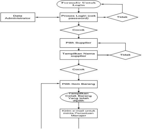
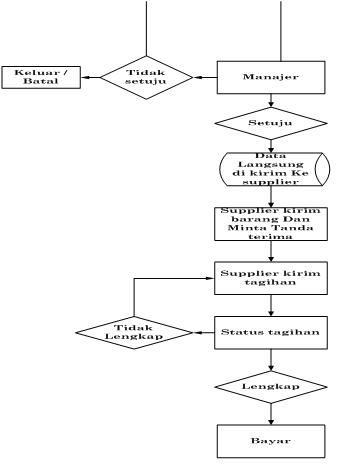

ANALISIS DAN DESAIN SISTEM INFORMASI (ADSI)
1. importance to develop an information system.
1. There is troubleshoots in the old system, the information from the system must continue to be developed. Example troubleshoots existing in the system
the information is old deceits that is not safe with the property company, and the truth of the data less well guaranted,
error does not accidentally cause the truth data is not guaranted, that is not operating efficiently, and not the choice of policy
applied.
2. Organizational growth, growth of the organization here who need the information more quickly, more data volume increases, changes
accounting principles bew. Caused by this change, then the old system is not effective anymore, so there must be the development of the system.
The old system that needs to be repaired or replaced because
several things:
1. The existence of problems (problems) that arise in the old system. The problems that arise can be:
– The old system irregularity
– Irregularity in the old system caused the old system can not operate in accordance with the expected.
– The growth of the organization
– Need more information on area, volume of data increasing, changes in accounting principles that should cause a new disusunnya
The new system, because the old system is not effective anymore and can not meet all the needs of more information is needed in management.
2. To seize opportunities.
In a tight market competition, efficiency, speed of information or time is very successful, or not to determine strategies and
plans that have been developed to achieve opportunity, opportunity and market opportunities, so that information technology should be used to
improve the provision of information to support decision-making processes undertaken by management.
3. There is an instruction from the leadership or government regulation
Preparation of the new system can also occur because of instruksiinstruksi from the top leadership or from outside organizations, such as
such as government regulations
In general the goal of developing information systems is
• There is a problem (problems)
• System Growth irregularity in the Organization
• To Reaching opportunities (opportunities)
• The instructions (directives)
2. the purpose of developing information systems
With the new system is expected to increase in going:
1. Performance, which can be measured from the throughput and response time.
Throughput: the number of jobs that can be done at a certain time
Response time: The average time between two pending transactions.
2. Quality of information presented
3. Advantage (lower costs). Related to the amount of resources used
4. Control (control)
5. Efficiency
6. Services
The general purpose of the development of information system are:
– Solve problems
– Reaching opportunities
– Meets the instructions provided
3.the organization’s expectations after implementing an information system
in this case aims to improve the performance of the company to become better and more forward from the previous. at any time the data will be updated
to become better than before.
4. Principles of the system:
1. Management system is developed.
2. System developed large capital investment.
3. System developed for the needs of the educated.
4. Stage of the work and tasks that must be made in the implementation of the development of the system (System Development Life Cycle).
5. System development process can not massage.
6. Do not be afraid to cancel the project.
7. The existence of documentation to guide in the development of the system.
5. system development life cycle model
System Development Life Cycle can be defined as a series of activities carried out by professionals and users of information system
to develop and implement information systems.
Waterfall model
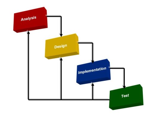
Waterfall model explanation:
1. Needs, the requirements in this process is a system analysis process does not need to collect from customers and / or top management of both areas
aspects of the business strategy, the system and the application or desired.
2. Design, at this stage we do not process analysis system, features that require, should be made of the application is also good for applications. Besides
that, here we also plan to start making the design of the system, such as the delegation, data structures, architecture, and because.
3. Implementation, the implementation process has continued from where we start the implementation of the design are made to be a program code read by the
language
Engine.
4. Verification, the verification process here, as the process of testing the system and / or application that is made. This process focuses on the logic
from the internal application that is made, as sure to check that the line coding. Besides, here we also have a test against
process of the possibility of system errors are made.
5. Maintenance, the maintenance process here will be repairs and maintenance of the system are made. Repair process is done here and
when the application or system that is made after the error to the customer, so it must need improvements to the system and processes
caused by or against the development of an OS so that applications needing to update.
Iteratif Model
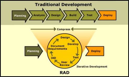
Iteratif model description:
Model Iteratif waterfall here with the same model, the same process found here, such as needs, design, implementation, and testing (verification).
1. Planning early, early into the planning process and / or ideas to create an initial system.
2. Planning, planning here will think that a mature system that is made of.
3. Needs, the same as in the process needs waterfall model, system analysis here does not need to collect from customers and the process or on the
management of the system and the application or desired.
4. Analysis and design, in this stage we do not process analysis system, which requires all the features, from applications that must also be made for both
application. In addition, here we also plan to start making the design of the system, such as the delegation, data structures, architecture,
and because.
5. Implementation, the implementation process has continued from where we start the implementation of the design are made to be a program code read by the
language
Engine.
6. Deployment, the Deployment purpose here has been the distribution process to the system are made, in the sense of distributing the system before hand
to the community before the test so that we know our system deficit.
7. Testing, testing process here we have a test and the system or application that is made. This process focuses on the logic
from the internal application that is made, ensure that each line coding check. Besides, here we also have a test against
process of the possibility of system errors are made.
8. Evaluation, evaluation process will improve the process here, the care and renewal of the system are made. Repair process is done here
and when the application or system that is made after the error to the customer, so that the process needs to be improvements to the system. Process
maintenance and updates made to development caused by the OS so that an application must be repaired again to update. Deep
reform process here will return to the process of planning, data collection (needs), systems analysis and design, implementation, Deployment,
testing and return for evaluation. if there is more development, then this cycle will be repeated again.
Spiral model
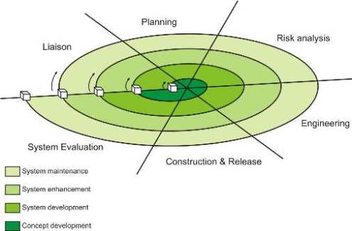
Spiral model of explanation:
Spiral model is divided into 4 task areas, namely:
1. Defining the purpose, in this process we will determine what will be the system, either from the output of the system.
2. Identify and risk, here we make the process of identification, planning and analyzing the risk may occur. In the process of
identification and planning, we must set before hand power source, the accuracy of the time, and other information related to the system
project we will create. While in the process of risk analysis here we do the analysis on the risks that might occur, between
management or technical.
3. Development and testing, in the process of development and testing we do is process engineering, construction and testing of
system are made. In the process of engineering and construction, we make the process of coding to create applications. Meanwhile, in the test, we perform
test against the system or application that we have created.
4. Plan next iteration, here we do plan the next iteration process and the evaluation or in the case of requests from customers for
changes to the system or application.
In this spiral model, this revolutionary process began, the team engineer surround system moving clockwise spiral from the
kernel. Spiral track the first round of development to produce products from the specification. Spiral rotation can be used to further develop
prototype, and develop a progressive version of the system will increase. Each track is passed to the planning area in the
project plan.
6. system development approach
There are several approaches to develop the system, namely
– Classical Approach,
– Structured approach,
– From The Bottom To Top,
– Approach from the Top to bottom.
Classical approach
Classical approach (classical approach) is also called the traditional approach (traditional approach) or Conventional approach (conventional
approach). Classical Approach methodology to develop the system by following the stages in the System Life Cycle. This approach emphasizes that
development will be successful when you follow the stages in the System Life Cycle. The problems that can arise in the approach
Classic is as follows:
1. Software development will be difficult
Less classical approach to provide tools and techniques in developing the system and as a result of this process of software development
does not become effective and difficult to be done by programmers. Case with other approaches that provide structured tools such as diagrams
flow data (data flow diagram), the dictionary data (data dictionary), the decision table (decision table). IPO diagram, chart structured (structured chart)
and others that allow the development of more effective software-based tools and techniques are
2. Treatment or maintenance system will be expensive
High cost of treatment in the classical approach the system is because the documentation system developed less complete and less structured.
This documentation is the result of tools and techniques used. Because the classical approach is less supported by tools and
techniques, the documentation to be incomplete and even less clear, but the structure, so that at the time of maintenance system
difficulties.
3. Possible errors of the system does not provide the classical approach to the way the system analyst to perform testing system, so the possibility
kesalahankesalahan system will become greater.
4. The success of the system less secure emphasis from classical approach is the work of personnel, personnel systems developer, not on the
system, but now we realize that the support and understanding of the system against the system under development is of vital
for successful system development project at the end.
Start early in 1970 appeared a new approach called structured approach. This approach is basically to try
system to provide analysts with the tools and techniques to develop the system in addition to the fixed idea of the system life cycle.
Structured approach (Structured Approach) has a structured approach to the equipment (tools) and teknikteknik needed in the development
system, so that the final results of the system will be developed in a system with well defined structure and clear. Some of the methodology
development of a structured system has been introduced in both bukubuku, as well as by companies consultants systems developers.
This methodology introduces the use of tools and techniques to develop a structured system.
The concept of structured system development is not a new concept. Assembly techniques in the manufacturing and design of circuits for electronic equipment
are two examples of this new concept that is used in many industries. This concept is still relatively new to use in developing a system
information system to produce products that satisfy users. Through this structured approach, permasalahanpermasalahan in a complex organization
can be solved and the results from the system will be easy to maintain, flexible, more satisfied users, have any documentation of good, right on
time, according to the budget cost, can improve productivity and quality will be better (error free).
– From Bottom To Top (Bottom-up Approach)
This approach starts from the bottom level of the organization, the operational level where the transaction is done. This approach starts from the
formulation
needs to handle the transaction and up to formulate the top-level information based on the needs of the transaction
it. This approach, characteristics of the classical approach. Approach from bottom to top when it is used in the analysis stage, the system is also called
the
term data analysis, because the pressure is to be data to be processed first, the information generated will follow the data.
– Approach from the Top to bottom (Top-down Approach)
Approach from the Top to bottom (Top-down Approach) starting from the top level organization, the level of planning strategies. This approach begins with
defining the goals and policies of the organization. The next step of this approach is the analysis of information needs. After
specified information needs, the process came down to the processing of transactions, namely the determination of output, input, databases, prosedurprosedur
operation and control.
This approach is also the characteristics structured approach. Top-down approach used at the stage when the system analyst is also the term
decision analysis, because the pressure is to be the information necessary for decision making by management first, then data
that need to be processed is defined to follow the required information.
– The piece (piecemeal approach)
Which emphasizes the development of an activity / application without considering the particular position in the information system or not
attention to the global organization’s goals (notice of targets, or that the application only).
– System approach (systems approach)
Given the information system as one integrated entity for their respective activities and emphasizes the application of the target organization
global.
– A comprehensive system (total-system approach)
The simultaneous development of the system as a whole, which will be difficult to develop (classical characteristics).
– The modular (modular approach)
The split with the complex system into a simple module, so the system more easily understood and developed, on time, easy
kept (most structured)
– Jump away (great loop approach)
Approaches that implement comprehensive changes simultaneously using advanced technology, that contain a high risk,
too expensive, difficult to develop because it is too complex.
– Developing approaches (evolutionary approach)
Approaches that apply only to advanced technology that requires only aplikasiaplikasi and continue to be developed for the next period
needs and existing technology.
6. System Development Methodology
Unitary method is a methodology, procedures, working concepts, rules and postulates that are used by a science, art or discipline
another. Method is a way, technique is not specific to systemic. System development methodology means the methods, procedures, working concepts, rules
and postulates that will be used to develop information systems. Algorithm is a sequence of procedures for deciding the problem.
Based on the classification methodology that can be grouped into three, namely:
7. classification methodology development
1. Functional decomposition methodology.
Emphasizeds this methodology in the solution of the system into smaller subsystems, so the more easily understood, designed and implemented. Own
This methodology, namely:
– HIPO (Hierarchy plus Input-Output-Proccess)
– Stepwise refinement (SR), or iterative refinement Stepwise (isr)
– Information-hidding
2. Data-oriented methodologies.
This methodology will emphasize on the characteristics of the data to be processed. This methodology can be grouped into two classes, namely:
a. Data flow-oriented methodology.
This methodology is based on the solution of the system intoes module based on the type of data elements and logic modules behavior insides system. Included in
This methodology, namely:
– SADT (Structured Analysis and Design Techniques)
– Composite design
– Structured Systems Analysis and Design (SSAD)
b. Methodology-oriented data structure.
This methodology emphasizeds structure of the input and output in the system. Belonging to this methodology, namely:
– JSD (Jakson’s System Development)
– W / O (Winner / Orr)
3. Determine the methodology.
This methodology is usually provided by the manufacturer of the software. Included in this methodology, namely:
– ISDOS (Information Systems Design and Optimization System)
– PLEXSYS
– PRIDE
– SDM/70
– Spectrum
– SRES and Srem
– Chapin’s approach
– DBo
– PAD
– HOS
– MSR
– PDL
8. In System Development Tools
Tools used in methodologies that are usually shaped picture or diagram, or graph. Graph form a system development tools,
namely:
– HIPO diagram
– Data flow diagram
– Structured chart
– SADT diagram
– Warnier / Orr
In addition to the graphic form tools, find some instruments have been established as general graphs Chart. Chart can be classified as follows:
1. Chart to describe the activity (activity charting).
System flowchart
Program flowchart that can be:
– Program logic flowchart
– Look up a computer program flowchart
– Paperwork or flowchart form flowchart
– Database relationship flowchart
Process flowchart
– Gantt chart
2. Layout charting
3. Staff relatioanship charting
– Work distribution chart
– Organization chart
9. In Engineering Development System
Techniques that can be used in the development of the system, namely:
1. Engineering project management,
the CPM (Critical Path Method) and pert (program evaluation and review technique). This technique is used for scheduling the project.
2. Fact finding techniques,
the techniques that can be used to collect data and find the facts that exist in the system studied, namely:
– Interview
– Observation
– Questionnaire
– Sample collected
3. Cost-effectiveness analysis or cost benefit analysis
4. Techniques for running meetings
5. Technical inspection / walkthrough.
10. System Analysis And Programmer
Analysis system is one that analyzes the system and learn to identify the problem and determine the needs of the user system.
Programmer who is writing the code for the program based on the particular application has been planned to get up that conducted by system analyst.
Functions and tasks of the analyst or a system as a mediator or the relationship between the user with the system programmer. Systems analyst must be aware correct knowledge about the two different technologies for the computer can communicate with the programmer and the knowledge of the applications developed so that they can communicate with the user’s system.
That knowledge needs Skill System Analyst
11. Find some eruditions knowledgeable and skills that must have system analyst, namely:
1. Knowledge and skills of data processing techniques, computer technology and computer programming.
– `Technical skills should have the skills in using tools and techniques for developing software applications with expertise in using computers.
– Technical knowledge must include knowledge about the hardware, technology, data communications, computer language, os, utilities, and another.
2. Knowledge about business in general.
This knowledge will want a system analyst for the system can communicate with the user.
3. Knowledge of quantitative methods.
System analyst uses many methods of quantitative models in building applications, such as dynamic programs, regresion, network, decision tree, Trends, and others such as simulation.
4. Trouble-shooting skills.
Systems analyst must have the ability to place troubleshoots complex faced by the business, divide the problem into parts, must be analyzed and then can go back into the system that can overcome troubleshoots.
5. Communication skills to provide staff.
Systems analyst must have the ability to conduct communications through the tongue or the article. This is a necessary skill in the interview, presentations, meetings and reports maker.
6. Provide skills to build staff connections.
Human factor is important insides system and different human characters with each other, so the need to build expertise connection to provide staff.
Information’s System
a. What is the system??
The meaning of system can divided into 2 meaning based on the approach of the system:
• Based on Procedure’s Approach System is the work’s network from procedure that related each other to finish the target.
• Based on Element’s Approach System is the group of elements that be interacted each other to reach the purpose. The system is work to reach a purpose (goal) & to reach a target (objective).
b. The Characteristic of System What about the component of system??
There are some points that explain about the characteristic of the system:
1. The component of System : Consist of a number of components which interact, what each other working along to form an unity. The example is Supra System that is a larger ones system.
2. Boundary : A system has a boundary to limiting system with environmental or other system outside its.
3. Environments : Environment is a media link between a subsystem with other subsystem.
4. Input : Entered energy into system can in the form of treatment input and signal input. The treatment input is entered energy system to can walk. While signal input is energy which in process to yield output.
5. Output : The result from processed energy and classified is become an output which good for and rest of dismissal.
6. Process : Process is the change an input become output.
7. Target (objective)/goal : Otherwise have the target then system operation there will be no utilizing of. The system is told succeed if it has reach the target/its goal.The connection’s media between one subsystem with the other subsystem. With this connection, the energy’s source can be possible flow from one subsystem to other subsystem.
c. The Classification of System
The system can be classified into several visions:
1. Abstract’s System & Physical’s System
The abstract’s system: The system can be idea that doesn’t appearance physically (Theology’s System).
The physical’s system: The system that appearance physically (Computer’s System).
2. Natural’s System & Human Imitation’s System
The natural’s system: The system that occur passing natural’s process, the system doesn’t made by human (circle of earth).
Human imitation’s system: The system that created by human (Human-Machine System).
3. The Specific’s System & Unspecific System
The specific’s system: The system operated with attitude that can be predicted.
The unspecific system: The system that future’s condition doesn’t be predicted.
4. The Closed System & Open’s System
The closed system: The system doesn’t relation and effect the outside’s environment.
The open’s system: The system is relation and effect the outside’s environment.
- The Basic’s Concept of Information
The information are the data that flow on the body of an organization. The data is describe the events and factual united.
- The Cycle of Information
- The Quality of Information
• Accurancy : The information must be free from the mistakes.
• Timeliness : The information that come to receiver mayn’t late.
• Relevant : That information has usual to user.
Mencari Inspirasi dalam Kejenuhan
Suatu ketika, disaat saya dihadapi oleh suatu masalah rumit, Dunia seakan tidak adil pada saya..
Seakan-akan saya sudah bosan hidup, muak menghadapi cerita bahagia orang-orang disamping tempat kita duduk, mereka tertawa terbahak-bahak layaknya orang yang hidup tanpa masalah… hidup dalam kesendirian, semua hampa, semua kosong, tiada sahabat, tiada orang terdekat, hanya angin kosong, debu dan sampah yang membusuk.
Dalam hidup, semua akan terjadi, kesedihan dan kesenangan datang tak terarah, tidak ada jadwal, semuanya datang begitu saja..Kapan Dunia adil, kapan kita lihat senyum pada setiap orang..tanpa kita lihat kesedihan, tanpa kita lihat penghinaan dan air mata. Semua bahagia, semua tertawa…
Tapi….
Ada semangat untuk bangkit, semangat menjadikan hidup yang lebih baik, menjadikan diri kita berarti buat orang lain yang mengerti akan perasaan kita…Inspirasi datang tak terduga saat kita menikmati kejenuhan itu, hayalan demi hayalan, ingatan demi ingatan seakan datang lagi menghampiri, membuat kita sadar akan apa yang kita perbuat dimasa lalu, dimasa kita menjadi orang paling bahagia dunia…
Kita Hadapi, perjuangkan…jangan buat kejenuhan menjadikanmu manusia yang tidak berguna…
SEMANGAT!!!
